Which boards make up the signer, and what each one does
Which small parts are needed, and which are only recommended
Start by gathering everything on this page. You may already own some of it: the build was designed around common hobby boards.
Prices are approximate: what the builder paid in Kenya, converted at about KSh 130 to US$1 (Central Bank of Kenya rate, November 2026). Expect them to vary where you shop.
Three boards make up the device, and a fourth (the USB-TTL adapter) programs and powers the camera board.
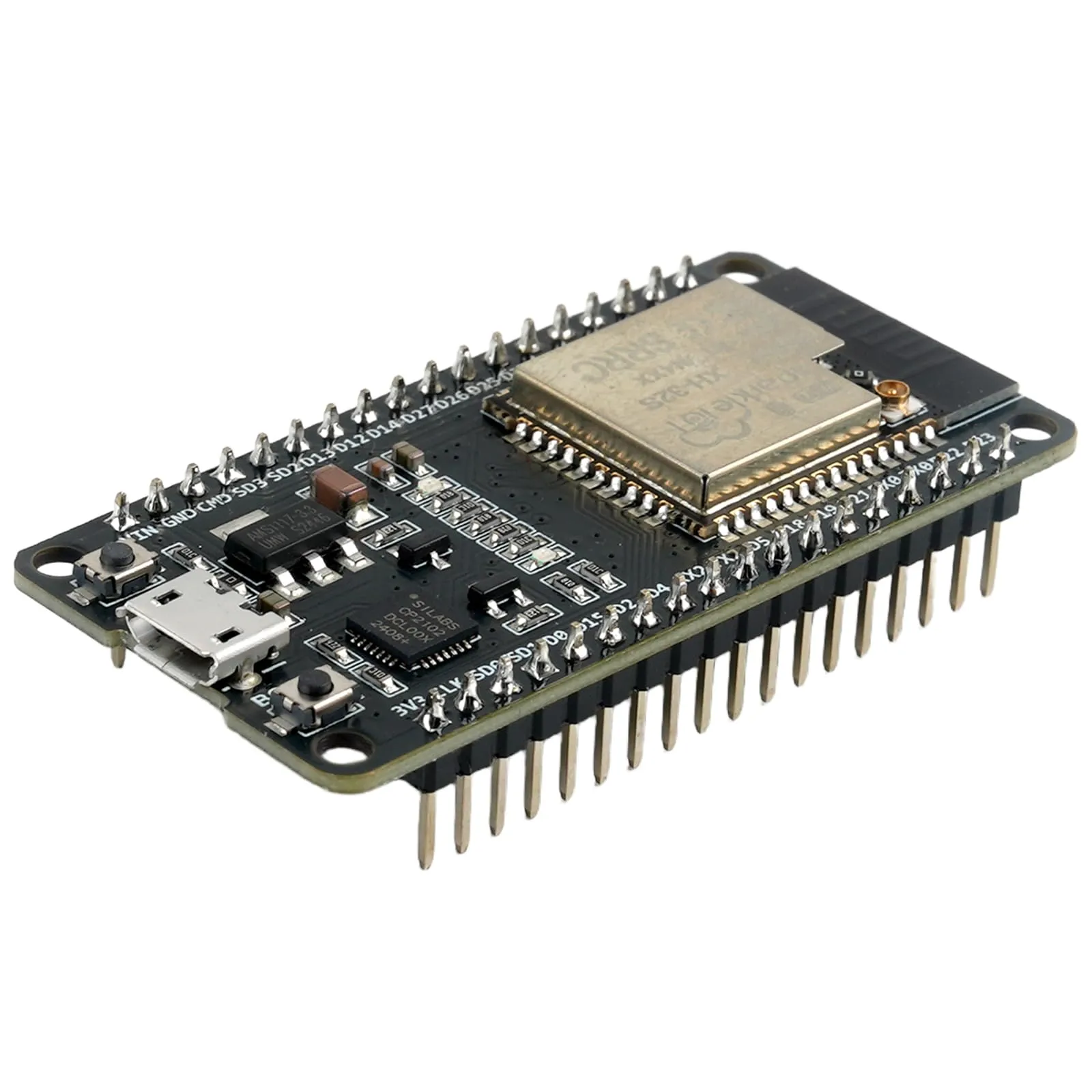
ESP32 DevKit (ESP32-WROOM-32)
The signer. Holds the seed in memory, checks the transaction and signs it.
Quantity
1
Cost
~$10
A classic ESP32 board with 520 KB of RAM and 4 MB of flash. It drives the touchscreen and receives scanned data from the camera board.
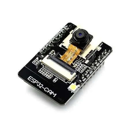
ESP32-CAM (AI-Thinker, OV2640 camera)
The QR scanner. Reads QR codes and sends what it reads to the signer over one wire.
Quantity
1
Cost
~$11.50
It has no USB port, so you program it through a USB-TTL adapter.
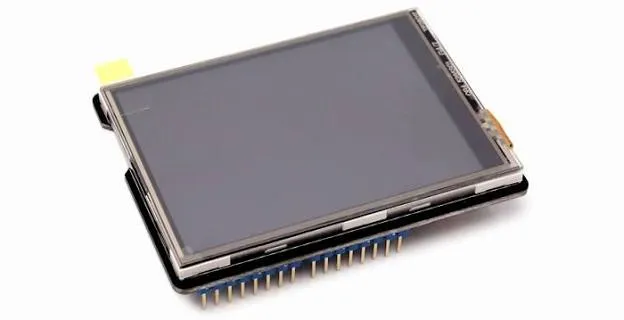
2.8" TFT touch shield
The screen and the buttons. You check every transaction on it and tap to approve or reject.
Quantity
1
Cost
~$14
ILI9341 display (ID 0x9341), 320×240 pixels, 8-bit parallel connection, resistive touch that shares pins with the display. It is wired to the DevKit with jumper wires instead of plugging into an Uno.
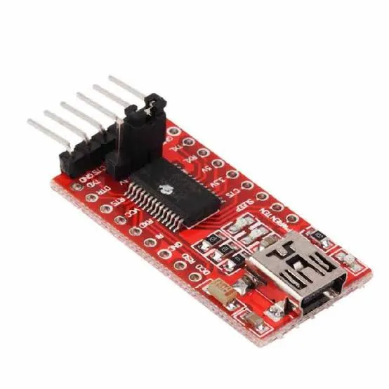
USB-TTL serial adapter (FTDI, CH340 or CP2102)
Programs the ESP32-CAM from your computer. In the tested setup it also powers the camera board.
Quantity
1
Cost
~$5.50
The tested build used an FT232 board whose single jumper sets both the supply and the logic level to 5V. That puts 5V on a camera-board pin, above the ESP32's rating, so a resistor divider on the adapter's TX line is recommended (see the divider part below).
16 for the touch shield, 2 for the camera link and 4 for the USB-TTL adapter (counted from the wiring tables).
Resistors, 1 kΩ and 2 kΩOptional
Bring the adapter's 5V signal down to about 3.3V for the camera board.
Quantity
1 of each
Cost
~$0.02 each
Recommended, but not fitted on the tested build. Adapter TX → 1 kΩ → CAM U0R, with 2 kΩ from CAM U0R to GND. At minimum, one 1–2.2 kΩ series resistor.
Resistor, 10 kΩOptional
Keeps the camera link quiet while the camera board is off or starting up.
Quantity
1
Cost
~$0.02
Optional, and not fitted on the tested build. A pull-up from DevKit GPIO34 to 3V3. Without it the signer receives junk bytes, which it safely throws away.
The two resistor parts are marked Optional. The tested build ran without them, but the 1 kΩ / 2 kΩ divider is recommended: Flashing the ESP32-CAM explains why.